Proper installation is the single most critical factor determining the lifespan, efficiency, and reliability of an industrial roots blower. A poorly installed blower will suffer from premature bearing failure, abnormal vibration, and costly downtime. Conversely, a correctly installed unit will run smoothly for years with minimal maintenance.
This guide provides a comprehensive, step-by-step procedure for installation of industrial roots blower and vacuum pump. We will cover everything from site preparation and foundation design to piping connection, lubrication, and initial startup testing, helping you avoid common pitfalls that plague field installations.
1. Pre-Installation Preparation & Site Requirements of Roots Blower
Before placing the blower on its foundation, thorough preparation ensures a smooth process and prevents issues later. This phase is about verifying what you have and where it will go.
1.1 Unboxing Inspection: Checking Critical Components
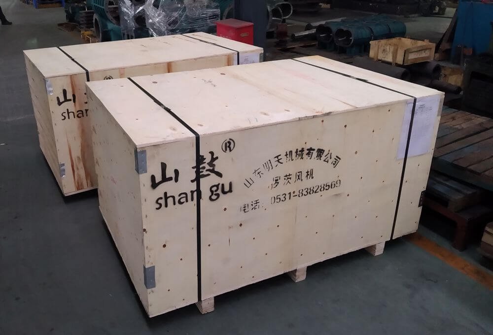
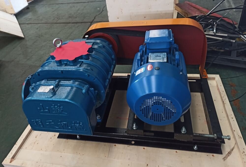
Upon receiving the equipment, conduct a meticulous inspection before signing off on the delivery. First, verify that the model number on the nameplate matches your purchase order and that all standard accessories listed on the factory packing list are present – common base, inlet/outlet silencers, flexible joints, pressure/vacuum gauge, and relief valve.
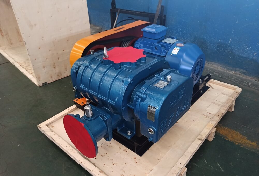
Second, inspect the physical condition. Look for any signs of shipping damage, such as dents in the casing or broken paint. Remove any temporary covers and manually rotate the impellers by hand via the coupling or pulley to feel for smooth, obstruction-free rotation. Pay special attention to the tri-lobe rotors; any nick or foreign object can compromise the tight internal clearances.
1.2 Environmental Conditions (Indoor vs. Outdoor Setup)
The blower’s operating environment directly impacts its performance and lifespan. For indoor installations, choose a bright, spacious, and low-dust area that allows ample space for routine maintenance, disassembly, and major overhauls. Ensure adequate ventilation to dissipate heat radiated from the blower body and motor.
For outdoor installations, mandatory precautions include a weatherproof canopy or roof to shield the unit from direct rain, snow, and sunlight. Special attention must be given to protecting the electric motor, V-belts (from moisture and UV degradation), and electrical components. The ambient operating temperature must never exceed 40°C (104°F); if it does, forced ventilation or cooling measures are required to prevent overheating.
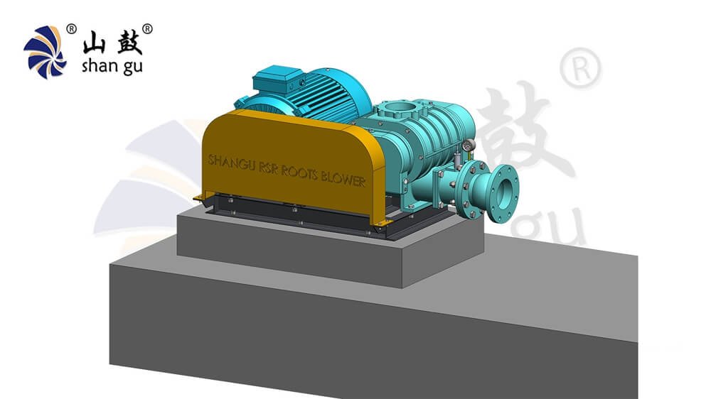
1.3 Foundation Design and Civil Engineering Requirements
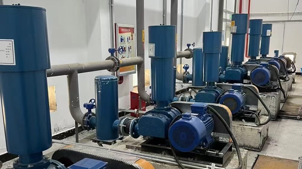
A roots blower is a positive-displacement machine that generates significant vibration and dynamic forces. Therefore, it must be mounted on a rigid, independent concrete foundation. Do not connect the blower’s foundation to existing building or wall foundations, as this will transmit vibrations and noise throughout the structure.
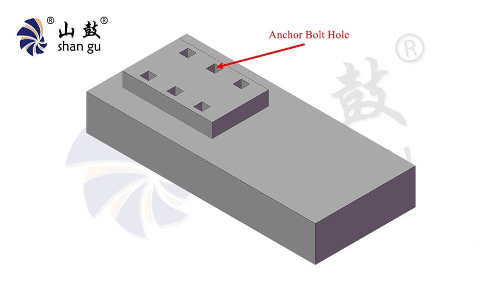
The foundation should be built on solid, undisturbed soil. The general recommendation is for the foundation to be 100-250 mm (4-10 inches) above the finished floor level and 800-1500 mm (32-60 inches) deep. The bearing surface should be 100-250 mm wider than the blower’s base plate on all sides. Use a concrete mix ratio of approximately 1 part cement, 2 parts sand, and 4 parts gravel. Leave adequately sized, cleanly formed anchor bolt holes in the wet concrete.
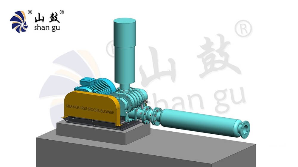
2. Step-by-Step Mechanical Installation Procedure of Roots Blower
With the foundation cured and the site prepared, the physical installation begins. Precision at this stage is key to preventing operational issues.
2.1 Blower Leveling and Grouting
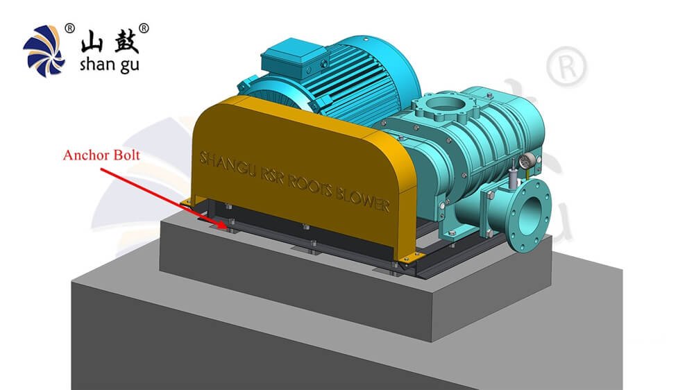
Place the Roots blower base onto the foundation, inserting steel shims (also called leveling pads or chocks) between the base and the concrete. These shims provide uniform support across the entire base. Use a precision spirit level on the machined flat surface of the blower casing or baseplate to level the unit. The allowable tolerance is 2mm per 1 meter of length (0.08 inches per 3.3 feet) .
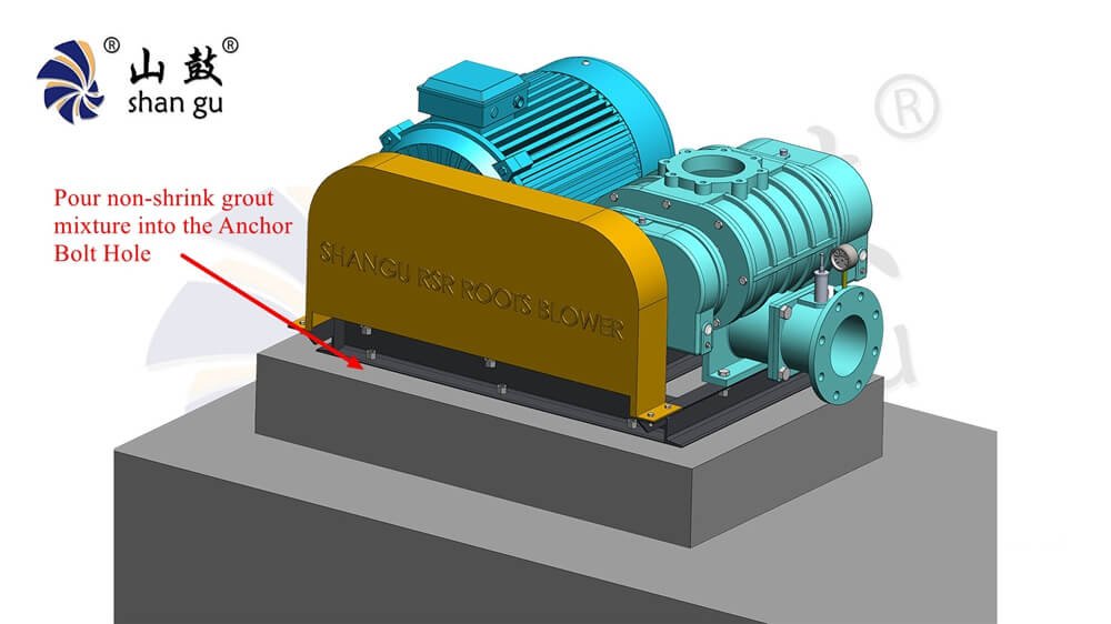
Once level, pour a non-shrink grout mixture (1 part cement, 2 parts sand) into the space between the base and the foundation, as well as into the anchor bolt holes. After the grout has fully hardened (typically several days), tighten the anchor bolts evenly and firmly.
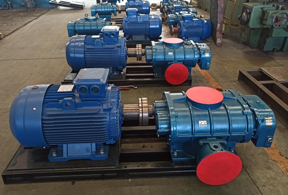
2.2 Drive System Alignment: Belt Drive vs. Direct Coupling
Misalignment is a leading cause of premature bearing and coupling failure. The alignment method depends on your drive configuration.
- For V-Belt Drive (SPA, SPB, SPC belts): Ensure the driver and driven pulleys are parallel. Use a straightedge or a laser alignment tool across the faces of both pulleys. The allowable deviation (β) is ≤ 20 minutes of a degree, with a parallelism offset (I) of ≤ 1.6a/1000, where ‘a’ is the center distance. After aligning, check belt tension using the deflection force method (as detailed in section 6.6 of the manual).
- For Direct Coupling (Elastic pin coupling): This requires more precise alignment. Use a dial indicator on both the radial (circumference) and axial (end face) surfaces of the coupling halves. The permissible radial and axial displacement varies by model, ranging from 0.3mm to 0.5mm depending on the coupling size.
The difficulty of achieving perfect alignment is significantly reduced when using blowers manufactured with high-precision CNC-machined casings and Class 5 accuracy timing gears, as these components ensure a perfectly true running base reference.
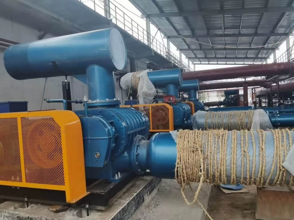
This is one of the most common and damaging installation mistakes. Do NOT force the inlet or discharge piping to align with the blower’s flanges. The full weight of the piping system and the stresses from thermal expansion must never be transferred to the blower casing.
First, thoroughly clean all pipes to remove rust, welding slag, and any other debris before connecting them to the blower. Then, install independent pipe supports to carry the load. Finally, always install flexible connectors (e.g., rubber expansion joints or stainless steel bellows) between the blower flanges and the rigid piping. These joints absorb thermal expansion and vibration, preventing casing distortion that can lead to internal rotor-to-casing contact.
3. Ancillary Equipment & Accessories Setup
A roots blower is part of a system. Correctly installing the auxiliary components is just as vital as installing the blower itself.
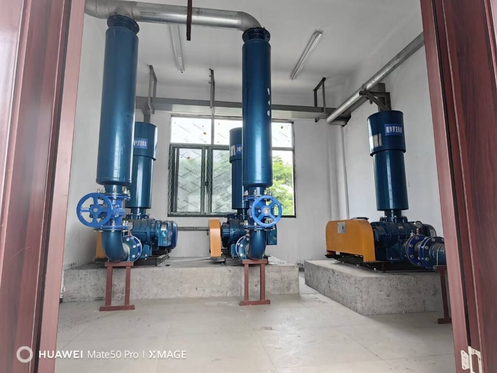
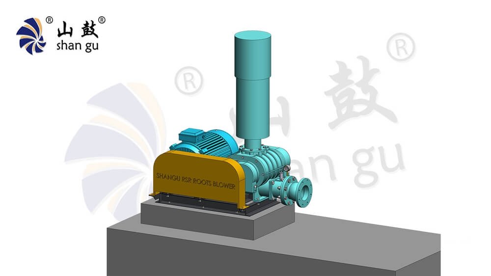
3.1 Inlet Silencer and Air Filter Installation
On the inlet side, always install a properly sized air filter or filter-silencer combination. The filter prevents airborne dust and particulates (which must be kept below 100mg/m³) from entering the blower and eroding the delicate internal clearances. Ensure the filter has adequate capacity for the blower’s maximum flow rate. These components are typically standard factory-supplied accessories. Plan for regular inspection and cleaning of the filter element.
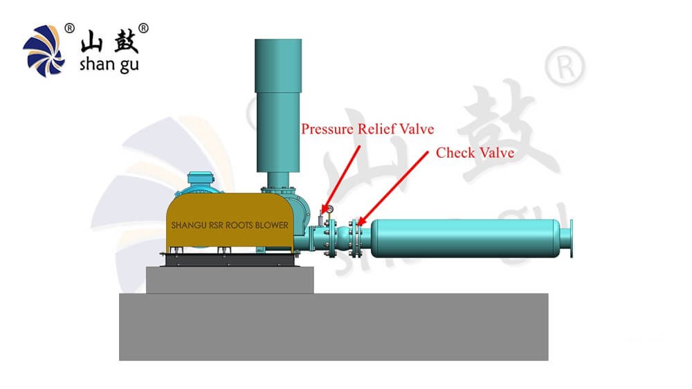
3.2 Pressure Relief Valve and Check Valve Alignment
On the discharge side (for blowers) or suction side (for vacuum pumps), two safety devices are mandatory.
- Relief Valve: This valve protects the blower from overloading. It must be installed closer to the blower than the check valve. The valve is pre-set at the factory; do not change its setting without understanding the consequences.
- Check Valve (One-way valve): Install this on the discharge line after the relief valve. It prevents high-pressure gas or system vacuum from flowing backward through the blower when it stops, which would otherwise cause the blower to act as a motor and spin backwards, leading to severe damage. Note: For DCV-type wafer check valves, the valve must be installed on a horizontal pipe with the handle pointing vertically upward.
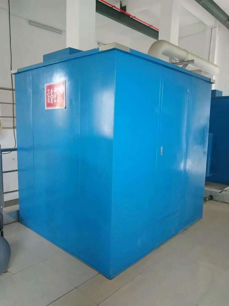
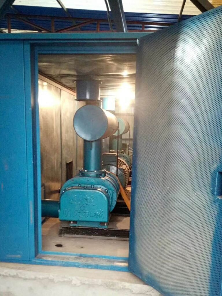
3.3 Noise Enclosure Setup (Optional)
For installations in noise-sensitive areas, a fully enclosed acoustic enclosure is highly recommended. A properly designed enclosure can reduce overall noise levels by approximately 5 dB or more. When setting up an enclosure, ensure it has adequate forced ventilation to prevent heat buildup, and provide easy access doors for routine service points like oil fill ports and drain plugs.
4. Pre-Commissioning & Lubrication Guide
Before the first electrical start, you must complete the lubrication and manual checks. These steps prevent “dry start” catastrophic failure.
4.1 Oil Selection & Double Oil Tank Initial Fill
Modern industrial roots blowers, particularly larger models, use a dual-oil-tank (double oil tank) system to separately lubricate the drive-side and gear-side bearings. This provides superior lubrication compared to older grease-packed bearings.
The factory may ship the blower without oil. Always check and fill before operation. Use a high-quality industrial gear oil, such as ISO VG 220# (e.g., CKC-220 medium-load gear oil) or a premium synthetic like Mobil SHC 630 or Shell Omala RL 220.
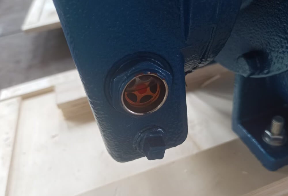
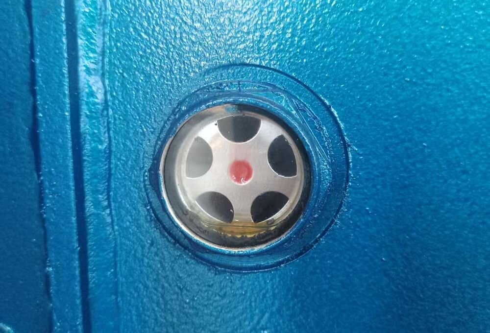
Fill the main tank and the drive-side tank (if present) until the oil level reaches the precise center of the sight glass. Do not overfill. Overfilling can cause oil foaming, high operating temperatures, and leaks. Conversely, an oil level more than 2mm below the center will lead to starvation and gear/bearing failure.
4.2 Manual Rotation & Direction Verification
Before applying power, perform a manual barring test. Rotate the blower shaft by hand for a full 5-10 revolutions using the coupling or a wrench on the pulley. You should feel smooth, even resistance with no scraping, binding, or grinding sounds. If you feel any interference, do not start the blower – investigate internal foreign objects or clearance issues.
After manual rotation, jog the electric motor (bump start) for just a second to verify the rotation direction. The blower shaft must rotate in the exact direction indicated by the arrow on the casing. Incorrect rotation can severely damage the blower due to reverse loading of the check valve and improper oil circulation.
5. No-Load Startup and Initial Run Testing
With the mechanical installation and pre-commissioning complete, the first powered run is a test of the entire system.
5.1 Step-by-Step Blower Commissioning Procedure
Follow this sequence for a safe startup:
- Ensure all valves in the inlet and discharge lines are fully open.
- Open the vent valve (or relief valve bypass) to its full open position. The blower must start under no-load (atmospheric) conditions.
- Start the motor. Listen for any unusual knocking or screeching sounds.
- Allow the blower to run unloaded for 5-10 minutes. This allows the lubricating oil to circulate and establish a proper film on the gears and bearings.
- After the unloaded run is stable, slowly close the vent valve to gradually load the blower to its operating pressure. Never close the valve rapidly, as this causes a dangerous pressure surge.
5.2 Monitoring Critical Parameters: Temperature, Pressure & Vibration
During the first 72 hours of operation, monitor and record these critical parameters frequently. This baseline data is invaluable for future predictive maintenance.
- Bearing Temperature: Must not exceed 95°C (203°F). For high-pressure air-cooled models, the limit is 145°C (293°F).
- Lubricating Oil Temperature: Must not exceed 65°C (149°F).
- Vibration Velocity: Measure on the bearing housings in vertical, horizontal, and axial directions. The maximum allowable value is 11.2 mm/s (RMS) .
- Discharge Pressure: Ensure it remains stable and does not exceed the nameplate rating.
Any rapid increase in temperature or vibration is a sign of a problem, such as over-tensioned belts, misalignment, or pipe stress. If detected, stop the blower immediately and investigate.
6. Frequently Asked Installation Mistakes (FAQ)
Q1: Why is my roots blower shaking violently after piping connection?
This is almost always due to pipe stress. The rigid piping is likely torqued or misaligned, forcing the blower casing out of its natural shape. This distorts the internal clearances, causing rotors to rub against the casing or each other. Check and refit the piping with flexible connectors.
Q2: Can I install a horizontally-designed roots blower vertically?
No. A horizontal roots blower is designed with specific lubrication channels, oil reservoirs, and bearing configurations that rely on gravity for proper oil return and distribution. Installing it vertically will cause immediate oil starvation, leading to rapid bearing and gear failure. Always follow the manufacturer’s approved orientation.
By meticulously following this step-by-step installation guide, you will ensure your industrial roots blower delivers optimal performance, maximum energy efficiency, and a long, trouble-free service life. Remember that a proper installation is the best form of preventive maintenance.